High Voltage BMS for Energy Storage and Industrial Battery Systems
A high-voltage battery management system (BMS) monitors battery conditions and coordinates protection and control in energy storage and industrial battery systems. Suitability for UPS, telecom backup, or electric mobility depends on the selected model and project requirements.
For battery pack manufacturers, distributors, wholesalers, and OEM/ODM buyers, selection starts with pack voltage, series cell count, current limits, and equipment interfaces. Share these requirements so candidate configurations and documentation can be reviewed before sampling.

Product video still. Model configuration and external connections may vary by project.
Built around your battery system
High-voltage battery projects differ in voltage, capacity, current, communication, connectors, protection settings, and control strategy. Share your battery system requirements so the appropriate architecture and interfaces can be reviewed.
What Does a High Voltage BMS Do?
A High Voltage BMS continuously monitors important battery parameters and helps coordinate protection and control across a larger battery system.
Monitor battery conditions
Key data can include individual cell voltage, total pack voltage, charge and discharge current, battery temperature, state of charge (SOC), state of health (SOH), balancing status, and system faults.
Coordinate protection
The BMS can help protect against overvoltage, undervoltage, overcurrent, short circuit, abnormal temperature, cell imbalance, and other operating faults.
Support system control
Monitoring and communication give system operators the information needed to review battery status and integrate the pack with connected equipment.
Modular High Voltage BMS Architecture
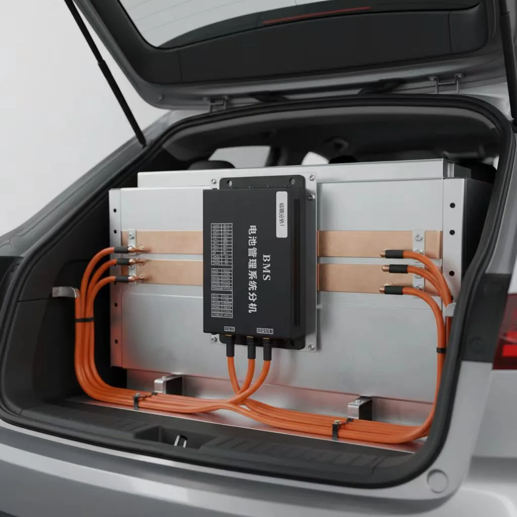
High-voltage systems typically connect multiple battery modules in series. A modular architecture normally includes cell monitoring units and a master BMS controller, allowing different system voltages, capacities, and project requirements to be considered.
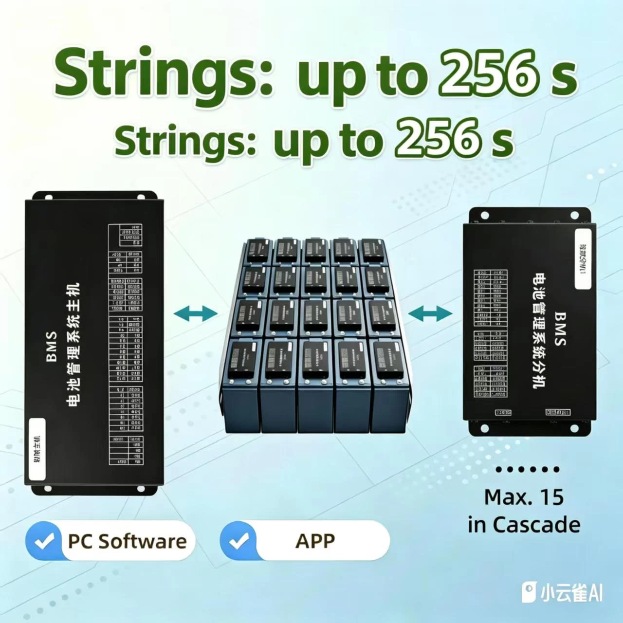
Master-Slave Cascading Architecture
A master controller coordinates cell monitoring units. Confirm the supported number of modules, PC software, and mobile app for the selected configuration.
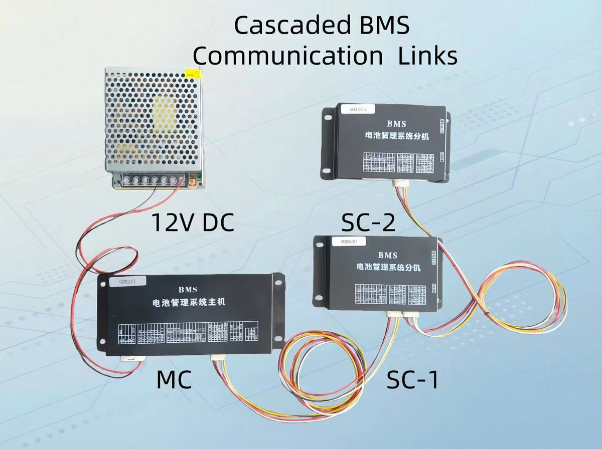
Cell monitoring units
Reference view of multiple cell monitoring units used in a modular BMS arrangement.
Communication and Inverter Integration
High Voltage BMS solutions can support CAN, RS485, UART, and custom communication protocols. Depending on the selected system, the BMS may exchange information with inverters, PCS, EMS, chargers, vehicle control units, or other external equipment.
Send the inverter, PCS, EMS, or charger model and protocol document. Confirm interface hardware, pinout, protocol version, and firmware compatibility during sample testing; matching a CAN or RS485 connector alone does not establish compatibility.
High Voltage BMS Technical Parameters
Use the information below as a starting point for high voltage BMS engineering review; specifications vary by model. Before bulk ordering, request the current datasheet, wiring diagram, sample test results, CAN/RS485 protocol details, and applicable compliance documents. Confirm voltage and current ratings, protection settings, and inverter or PCS compatibility for the exact hardware revision.
| NO. | Function | Content | Remarks |
|---|---|---|---|
| 1 | Built-in Bluetooth | Supports Android devices | Connects via Bluetooth to view parameters and configure BMS settings |
| 2 | PC connection | PC software with Chinese and English language support | Connect via RS485/USB to view parameters, configure settings, and update firmware. |
| 3 | Detectable Cell Count | 5–16 sets of lithium batteries *16 | Modify the number of battery strings on both the master and slave units using a host computer, app, or LED display. |
| 4 | Supported Cell Types | Lithium-ion, lithium iron phosphate, lithium titanium | Connects via Bluetooth to configure the number of cells |
| 5 | Power Supply | The motherboard is powered by a separate wiring connection. | Input range: 80–400 V DC or 200–1200 V DC; automatically switches to low-power mode |
| 6 | Single Cell Voltage Detection | 0–5 V | Error across the operating range: <20 mV; typical error: <10 mV Resolution: 1 mV |
| 9 | Temperature Detection | −40 to 125 °C | The host unit features one built-in MOS channel and one built-in equalization channel, with support for two external battery channels and two relay temperature detection channels. |
| 11 | Current Detection | Sampling interval: <250 ms; accuracy: 5% | Shunt is standard,-300A to 300A at 75 MV, The remaining specifications of the diverters can be customized individually. |
| 12 | SOC Estimation Accuracy | Error < 5% (operational conditions) | Bluetooth connectivity for setting cell type (adaptive change in single-cell protection voltage) |
| 14 | Short Circuit Protection | Supported (adjustable) | Can be configured |
| 15 | Fault Records | Supported (400 cycle records) | View system logs via the Bluetooth app or PC software |
| 16 | Operating Power Consumption | <100 μA (no communication, in sleep mode) | <20 mA (in standby mode) |
| 17 | Operating Temperature | −20 to 70 °C | Operating humidity: 5–90% RH |
| 18 | Storage Temperature | −40 to 85 °C | Storage humidity: 0–90% RH |
| 19 | Weight-1 | <400 g | <400 g |
| 20 | Weight-2 | <400 g | <400 g |
| 21 | 485 Interface | Standard configuration | 1 channel: Supports host-based management/screen display |
| 24 | Relay control | The precharge/discharge/charge relay can control a current of 1 A. | |
| 25 | Accessory Package | One complete wiring kit | The communication lines between the master and slave devices are configured based on the number of slave boards. |
| 26 | 4.3-inch LED touchscreen | Standard configuration | Monitor battery details, modify serial numbers, and enable or disable charging and discharging |
Features requiring model-specific evidence
The items below are not confirmed as standard or available options for this reference model. Standard hardware and optional modules must be identified from the manufacturer's model and revision documents. External services are separate from board functions.
| Item to verify | Evidence needed before it can be quoted as a capability |
|---|---|
| Balancing method and current | Hardware topology, exact model/revision, current, enabling conditions and thermal limits. Parameter changes alone do not create active-balancing hardware. |
| Thermal-runaway pre-warning | Sensor/BOM details, algorithm description and model-specific validation records; gas/impedance sensing is not established. |
| CAN and isolated communication | Model-specific connector/pinout, interface isolation specification, protocol version and firmware/BOM identifying standard versus optional hardware. |
| LTE and GNSS | External communication module/BOM, antenna arrangement, supported services and integration requirements. Not established as an included board function. |
| Cloud monitoring and OTA | Required external modules/services, supported firmware, update security and manufacturer documentation. Not established as an included board function. |
| Low-temperature charging | Cell-maker charging limits, measured lockout/recovery behavior and any separately specified heating hardware. A heater or a protection setting is not blanket permission to charge cold cells. |
| Regenerative operation | Controller/charger interface, accepted charging-current limits and model-specific protection/validation data. |
| Other withdrawn safety or performance claims | Model-specific test evidence for standby current, enclosure/IP protection, pre-charge hardware and measurement conditions where applicable. |
High Voltage BMS Applications
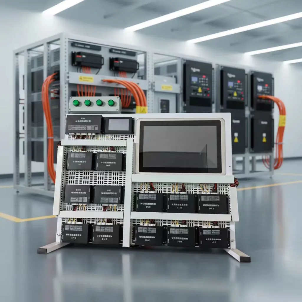
Energy storage
Commercial and industrial energy storage, solar and renewable energy storage, and large-scale battery energy storage systems can require modular battery monitoring and system communication.
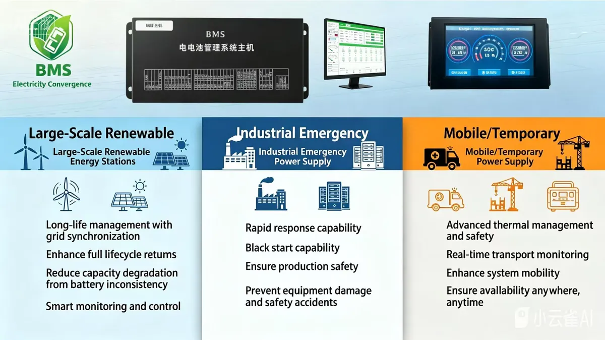
Backup and telecom
UPS, backup power, and telecom battery systems need a BMS selected around the battery configuration and the connected power equipment.
Industrial and electric mobility
Industrial lithium battery packs, electric vehicles, and special vehicles may have application-specific voltage, current, communication, and control requirements.
Explore related pages for energy storage BMS and industrial equipment BMS.
High Voltage BMS Frequently Asked Questions
What information does a High Voltage BMS monitor?
Depending on the system, it can monitor cell and pack voltage, current, temperature, SOC, SOH, balancing status, and fault conditions.
Why use a modular BMS architecture?
High-voltage systems often contain several battery modules in series. A master controller with cell monitoring units can help manage a larger pack while accommodating different project configurations.
Can the BMS communicate over CAN or RS485?
CAN, RS485, UART, and custom protocols are options to review. The selected interface and protocol must be checked against the inverter, PCS, EMS, charger, or vehicle system used in the project.
What should I send for an OEM High Voltage BMS inquiry?
Send battery chemistry, series count, pack voltage, capacity, charge and discharge current, required communication protocol, and application details.
Need Help Choosing a High Voltage BMS?
Send your battery chemistry, series cell count, pack voltage, capacity, charge and discharge current, equipment model, communication protocol, operating conditions, and target quantity. We can review the BMS architecture, integration requirements, and OEM/ODM scope.